Gates have inputs and outputs. Using Binary numbers, the charts of inputs would keep adding up until all of them reached 1. After that, the output such as a LED for example, would light up.
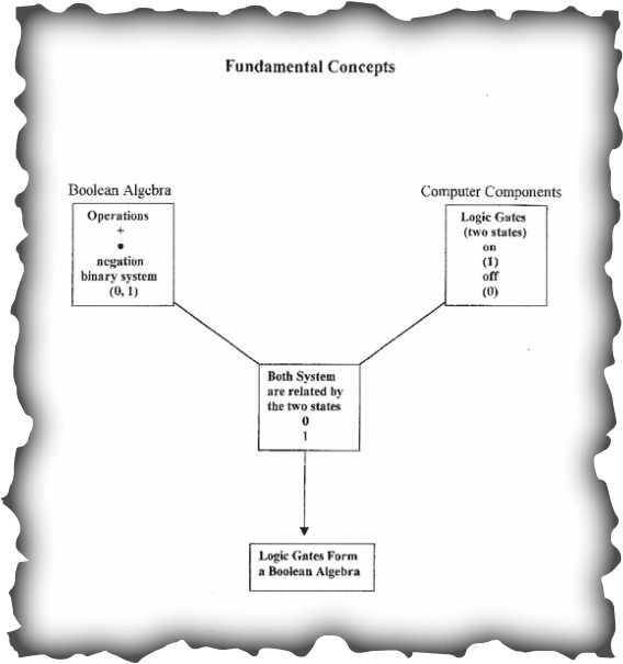
This explains how logic gates form a Boolean algebra.
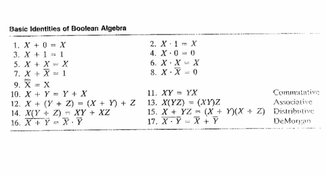
These are different equations of Boolean Algebra.
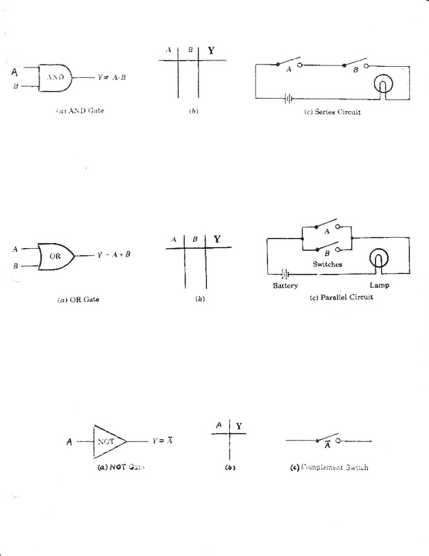
These are the three basic logic gates: AND, OR, & NOT.
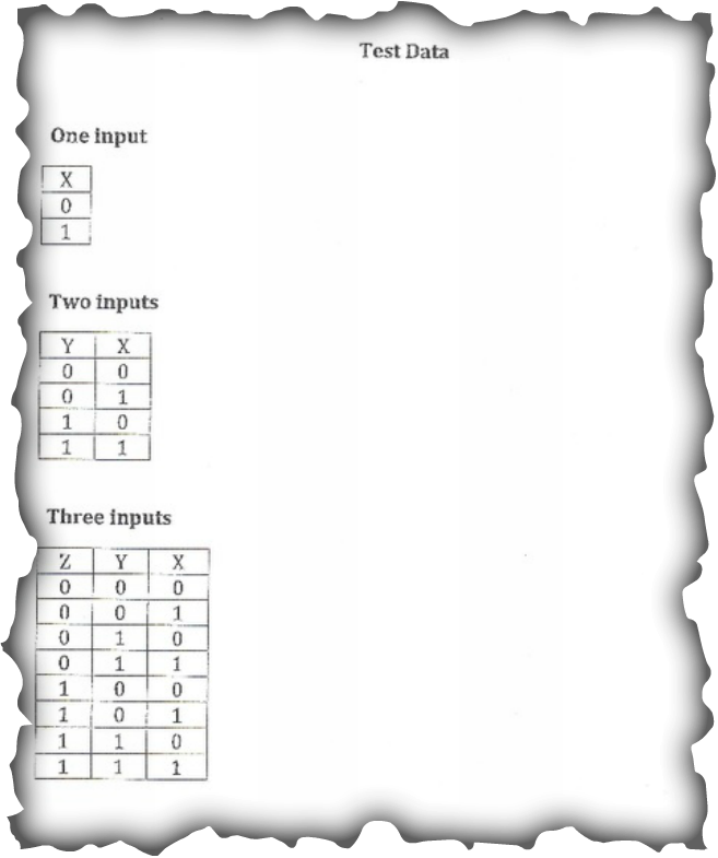
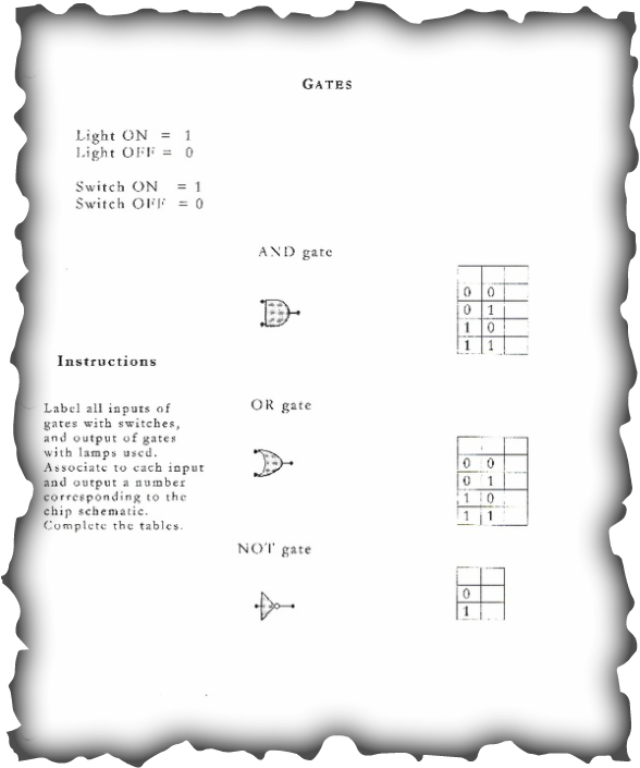
These are test data instructions of the logic gates.
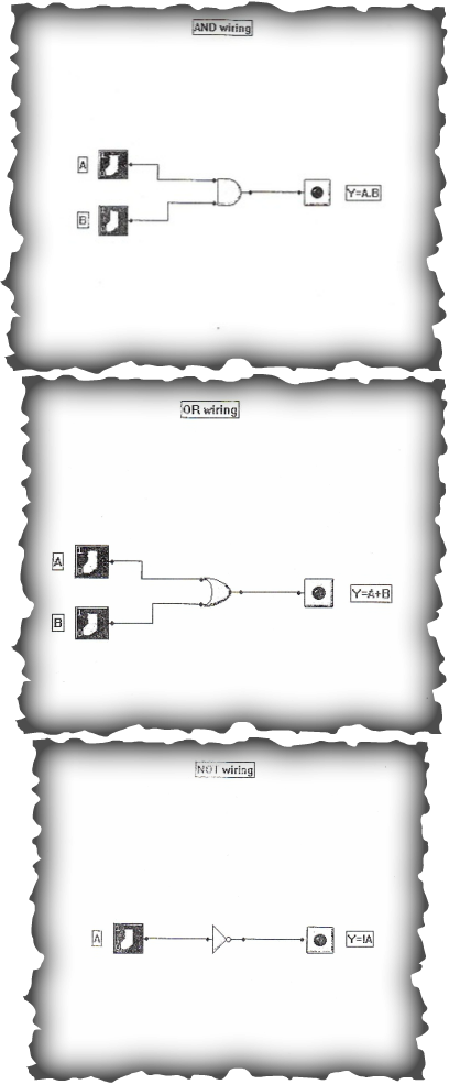
These are the wiring of the three logic gates.
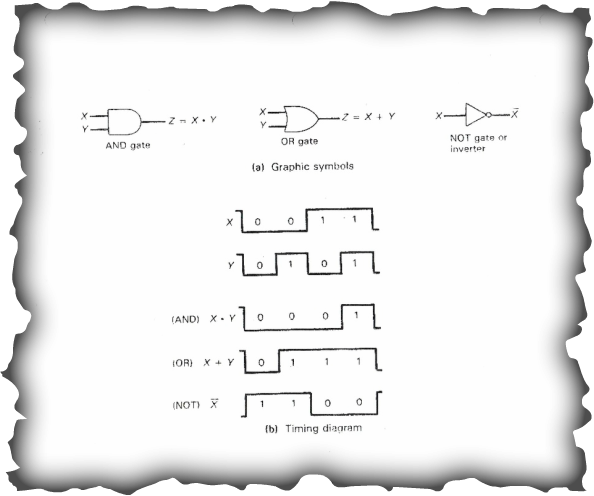
In this image below, you'll see how logic gates form Boolean algebra.
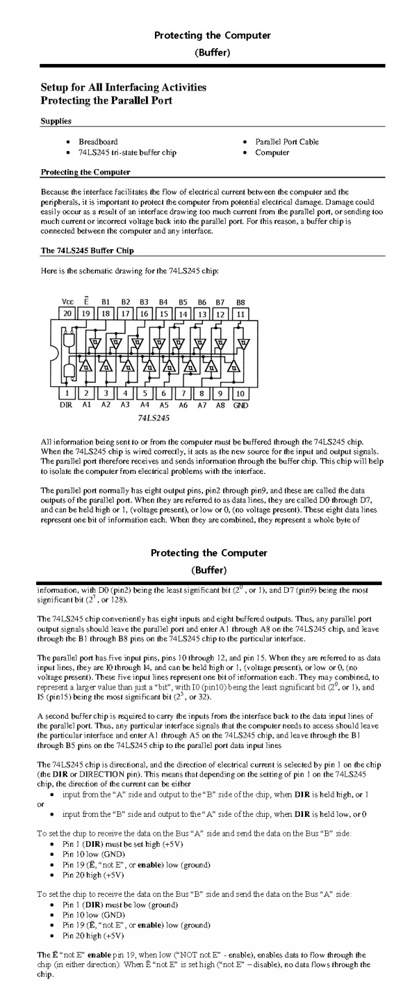
This explains about the buffer chip.